First Software
With the hardware assembled and the CPLD programmed it’s time to start writing some code to test and see if the hardware is working.
The first program to test is just a simple loop. This will just read the code from the ROM and execute several instructions on the CPU and repeat endlessly.
stack_top   EQU   $100000          ; stack at the top of RAM

            ORG   $F80000          ; start address for the ROM
start

Vec_stack
    dc.l    stack_top              ; initial stack pointer
Vec_start
    dc.l    startup                ; initial program counter

startup
    move.w #$2700,SR
loop
    add.b   #1,d0
    add.b   #2,d1
    add.b   #3,d2
    add.b   #4,d3
    add.b   #5,d4
    add.b   #6,d5
    add.b   #7,d6
    add.b   #8,d7

    bra loop

    END startup
The code was assembled, programmed onto the EEPROMS, plugged into the board and the board was switched on.
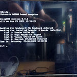
Success!
The HALT and RESET leds were clear and the RUN led was on. It appears that the first attempt at running the code was successful!
Partly out of disbelief that the first test just worked and also to confirm that the code was indeed running I fired up the oscilloscope and done some checking on the signal lines. Signal lines all look good and it seems that the CPU is quite happily chugging along running in an infinite loop.
Boosted by this success it was time to try something a little more complicated, this time write a message out over the serial port.
        include 'ddraig.inc'
        include 'DUART.inc'

STACK_BASE      EQU     SRAM_END+1

        org ROM_START
start
        dc.l STACK_BASE
        dc.l startup

startup
        lea DUART_BASE,A0
        move.b #$30,DUART_CRA(A0)               ; reset transmitter
        move.b #$20,DUART_CRA(A0)               ; reset reciever
        move.b #$10,DUART_CRA(A0)               ; reset MR pointer to MRx1

        move.b #$00,DUART_ACR(A0)               ; select BAUD rate set 1
        move.b #$BB,DUART_CSRA(A0)              ; set TX & RX to 9600 BAUD
        move.b #$93,DUART_MR1A(A0)              ; set 8 bits,no parity,character mode,RxRDY IRQ,RxRTS enabled
        move.b #$37,DUART_MR2A(A0)              ; $37 Normal mode,enable TxRTS & TxCTS,1 stop bit
        move.b #$05,DUART_CRA(A0)               ; enable Receiver and Transmitter
        move.b #$01,DUART_OPRSET(A0)            ; $01 assert RTS (Only needed if applicable bits set in MRxA?)
        lea.l string,A2                         ; Load the string to send

loop
        move.l #00,D1

check_buffer
        move.b DUART_SRA(A0),D0                 ; Get the status register
        and.b #TxRDY,D0                         ; Check if the transmit bffer is empty
        beq check_buffer

        move.b (A2,D1),DUART_TBA(A0)
        cmp.b #$0a,(A2,D1)                      ; Check if it's the last character
        beq loop
        addq #1,D1

        jmp check_buffer

string
        dc.b 'Y Ddraig is alive!',$0d,$0a

        END startup
Too good to be true
Switch the computer on and initially it all looks good, RUN led is on but there’s nothing on the serial port. Time for some debugging, is there a problem in the code I’ve written or is this an issue with the hardware.
First thing to check is the address decoding is correct. Checking that the CS_DUART line is active shows that nothing is happening. Checking the CPLD code and that seems correct and in simulation at least it should be outputting the CS_DUART signal. This also highlights another issue as well. If the duart is never responding then why is the program still running? If the DTACK signal is never asserted by the duart then the program should stop.
Testing the DTACK signal on the CPU sees that it’s constantly low so the CPU is never waiting for it to respond. The DTACK can come from 4 sources, time to see which one is at fault.
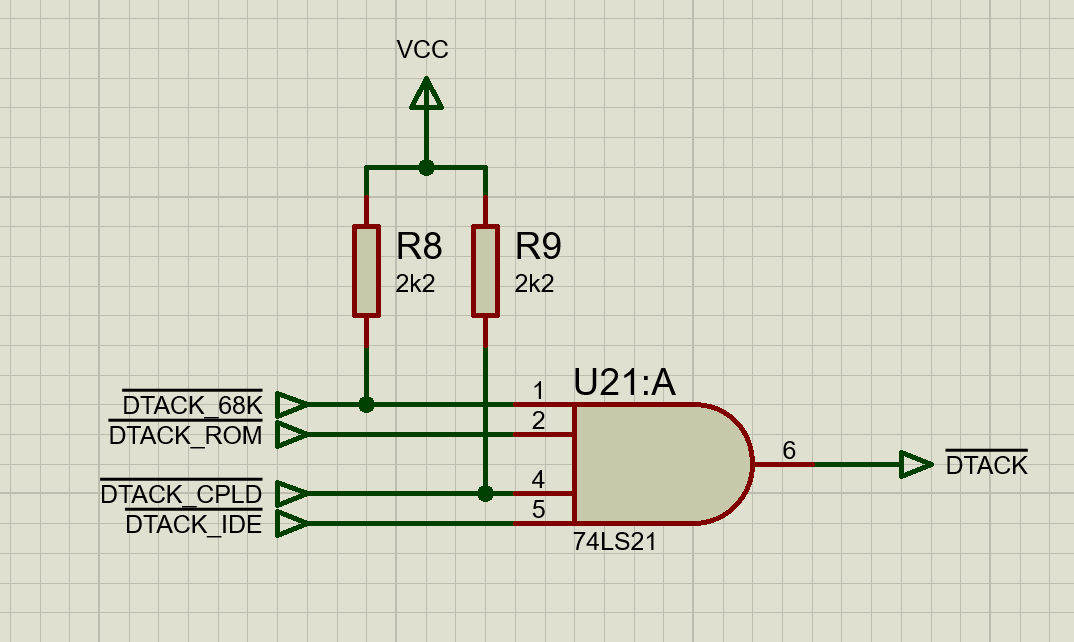
Testing each of the DTACK inputs shows that the DTACK_ROM is active, DTACK_68K and DTACK_CPLD are high but the DTACK_IDE is low. As there’s nothing connected to the IDE interface at present then this seems suspicious. The IORDY signal from the IDE is pulled low and inverted to make the DTACK signal.
Checking the inverter it was showing that both the input and output were low. Changing the chip made no difference but I noticed that the input wasn’t quite at 0 but floating a little above. A bad solder joint on the pull down resistor was the case and once fixed then the DTACK signal was working as expected. Running the code this time and the CPU stop with the HALT led on.
This still left the issue of the duart chip select not working. Tested the address inputs on the CPLD and found that A18 was low. A bad solder joint on the CPU was the issue this time.
Still no serial data
With the address lines now working the CPLD is generating the CS_DUART signal but there’s still no DTACK coming back from the duart. Further investigation on the problem found that the reset on the duart was stuck low, again due to a bad solder joint.
At this point it’s time to put testing on hold for a little while. So far the problems encountered have been down to bad solder joints so it would make sense to rework the soldering joints before proceeding any further. Hopefully this will help prevent a few errors like the ones found so far.