Hardware
Y Ddraig hardware
This page contains information for revision 2 of the board. Information for the latest revision of the hardware can be found here.
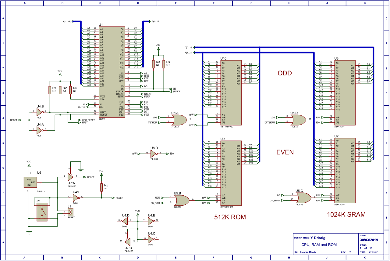
CPU, RAM and ROM
The CPU used by Y Ddraig is the Motorola MC68000 running at 10 MHz. The 68000 has a 16-bit data bus and 24-bit address bus internally runs as a full 32-bit machine. The 68000 has 8 general purpose data registers D0-D7 and 8 address registers A0-A7. The address register A7 is also used as a special purpose register holding the stack pointer.
There is 512K of ROM available supplied by two 256K x 8-bit SST39SF020 devices for the ODD and EVEN addresses.
RAM is provided by two 512K x 8-bit AS6C4008 Static RAM devices giving a total of 1024K of available memory. There is also the option of adding an additional Dynamic RAM to expand the memory up to a total of 9MB.
Memory Mapping
As the MC68000 is a memory mapped device the address decoding is handled by a Xilinx XC95C108 CPLD. In addition to the address decoding the CPLD is also used as the DRAM controller.
The memory map is as follows:
| Device | Start Address | End Address |
|---|---|---|
| Static Ram | 0x000000 | 0x0FFFFF |
| Dynamic RAM | 0x100000 | 0x900000 |
| DUART | 0xF7F000 | 0xF7F0FF |
| YM2151 | 0xF7F100 | 0xF7F1FF |
| PIT | 0xF7F200 | 0xF7F2FF |
| KBD | 0xF7F300 | 0xF7F3FF |
| IDE | 0xF7F400 | 0xF7F4FF |
| ETHERNET | 0xF7F500 | 0xF7F5FF |
| RTC | 0xF7F600 | 0xF7F6FF |
| VDP | 0xF7F700 | 0xF7F7FF |
| ROM | 0xF80000 | 0xFFFFFF |
Dynamic RAM
Y Ddraig support up to a maximum of 8MB Dynamic RAM via two 4MB 30-Pin SIMMs. Smaller values can be used but both SIMMS have to be of the same type.
The XC95108 CPLD handles read and write access to the DRAM and also handles the CAS-before-RAS refresh. Any wait state that have to be added are done using the DRAM DTACK signal.
Serial port
A RS-232 serial port is provided using a MC68681 Dual Universal Asynchronous Receiver/Transmitter. Although two channels are available in the DUART only a single channel is being used on this design.
Timer and Joystick ports
A MC68230 Parallel Interface/Timer is used to provide a programmable timer and two of the IO ports are used for the joystick interface.
Keyboard and mouse
The keyboard and mouse are connected via the two PS/2 ports at the rear of the computer and are controlled by a VT82C42 keyboard controller, a 80C42 compatible device.
Video display processor
Video is provided by a Yamaha V9990. The V9990 was used in video expansion cartridges for the MSX range of computers such as the Sunrise GFX9000.
| Specifications |
|---|
| Up to 512K Video RAM |
| 2 Pattern display modes and 8 bitmap modes |
| 32,768 colors can be displayed |
| Omnidirectional smooth scrolling |
| Hardware accelerated drawing functions |
| 125 Sprites in pattern mode or 2 cursors in bitmap mode |
Supported resolutions
| Mode | Resolution | Colors (bpp) | Sprites | Scan rate | Remark |
|---|---|---|---|---|---|
| P1 | 256×212 (256×424) | 4 | 125x 16×16 16c | 15.7 kHz | 2 independent planes |
| P2 | 512×212 (512×424) | 4 | 125x 16×16 16c | 15.7 kHz | Pattern mode |
| B0 | 192×240 (192×480) | 16, 8, 4 or 2 | 2x 32×32 4c | 15.7 kHz | undocumented overscan mode (no borders) |
| B1 | 256×212 (256×424) | 16, 8, 4 or 2 | 2x 32×32 4c | 15.7 kHz | bitmapped mode |
| B2 | 384×240 (384×480) | 16, 8, 4 or 2 | 2x 32×32 4c | 15.7 kHz | overscan (no borders) |
| B3 | 512×212 (512×424) | 16, 8, 4 or 2 | 2x 32×32 4c | 15.7 kHz | bitmapped mode |
| B4 | 768×240 (768×480) | 4 or 2 | 2x 32×32 4c | 15.7 kHz | overscan (no borders) |
| B5 | 640×400 | 4 or 2 | 2x 32×32 4c | 25.3 kHz | |
| B6 | 640×480 | 4 or 2 | 2x 32×32 4c | 31.5 kHz | needs a 25.2MHz oscillator |
| B7 | 1024×212 (1024×424) | 2x 32×32 | 4c | 15.7 kHz | undocumented mode |
Resolutions between parentheses () are in interlacing mode. When interlaced mode is used, there is no need to split odd and even lines between pages to have a doubled vertical resolution image.
Supported color modes
The Yamaha V9990 is capable of displaying a total of 32768 colors via its 15 bit hardware color DAC.
The above mentioned resolutions can be combined with the palette systems below, so a lot of different screen configurations are possible.
- B4, B5 and B6 video modes don’t support 8 or 16 bits per pixel color modes.
- P1 and P2 only support 4 bits per pixel. There are four independent 16 color palettes available however, so each plane (2 on P1 mode, 1 on P2 mode) can select one of the 4 palettes independently, and each sprite can select its own palette as well. This way, color count can be higher on these modes.
| bits/pixel | colours | system |
|---|---|---|
| 16 | 32768 | simultaneously |
| 8 | 64 | out of a palette of 32768 |
| 8 | 256 | like SCREEN 8 (fixed palette) |
| 8 | 19268 | like SCREEN 12 (YJK) |
| 8 | 19268 | YUV (better colour distribution than YJK) |
| 4 | 16 | out of a palette of 32768 |
| 2 | 4 | out of a palette of 32768 |
Hardware sprites/cursors
In pattern modes:
- 125 different sprites can be displayed at the same time, and a maximum of 16 sprites on the same scanline.
- Sprites can use any 16x16 pixels area from the pattern generator table.
- Since every pattern on P-modes are 4 bpp encoded, sprites can have 15 colors (plus one transparent).
- Each sprite can choose its own palette from the 4 palettes available.
In bitmap modes:
- Sprites are not supported. Cursors are supported instead.
- 2 cursors can be displayed at the same time. There are no scanline limitations for cursors.
- Cursors have their own 32 x 32 pixels allocated on VRAM.
- Each cursor can have its own 2 colors, a third (EOR) color and transparent color.
(V9990 information from msx.org)
Sound system
Sound is provided by a Yamaha YM2151 FM Operator Type-M which is an eight-channel, four-operator sound chip.
The YM2151 is connected to YM3012 2-Channel serial DAC to provide the audio output.
IDE interface
The IDE interface provides a 16-bit connection to allow a hard drive or a compact flash card (with suitable adaptor) to be used for mass storage. A jumper link connected to pin 20 allows 5 volts to be supplied if using a CF card which is supported by several CF adaptor interfaces.
Real-time clock
The RTC is provided by a 4-bit RTC-72421. A battery backup is provided so that the date and time is not lost when the computer is switched off.
Ethernet controller
Networking is provided by the CS8900A is a low-cost Ethernet LAN controller. The CS8900A includes on-chip RAM, 10Base-T transmit-and-receive filters and a direct ISA-Bus interface.
Interrupts
There are three input pins available on the 68000, called IPL0, IPL1, and IPL2. IPL stands for Interrupt Priority Level and each has a priority with 7 being the highest priority. These can be masked by the IPL bits in the status register. Inputs to the computer are put on the higher priority interrupts but in most cases the software doesn’t need any particular priories assigned to the levels. The interrupt priority is generated using a 74LS148 8 to 3 line encoder.
Interrupt table
| Priority | Interrupt |
|---|---|
| 1 | V9990 VBL and programmed interrupts |
| 2 | YM2151 timer interrupt |
| 3 | IDE interface interrupt |
| 4 | Ethernet interrupt |
| 5 | PIT timer interrupt |
| 6 | Serial port interrupt |
| 7 | Keyboard and mouse interrupt |
Board information
Schematic
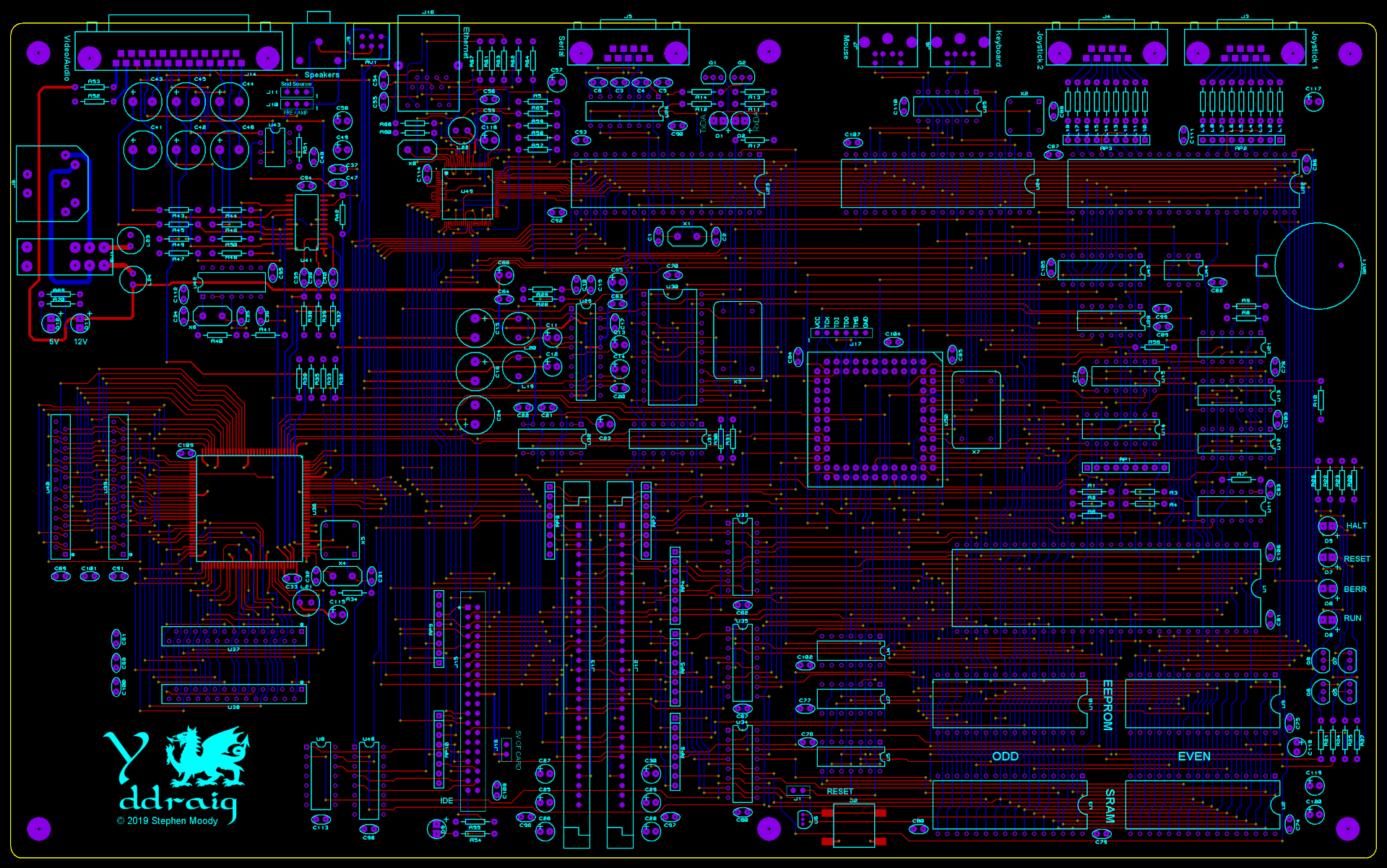
PCB Layout